
- Published on
What is Protective Device Isolation?
- Authors

- Name
- Ben Gibb
Protective device isolation isn't just another checkbox in arc flash studies — it's a critical factor that needs to be understood to ensure electrical system safety.
Protective Device Isolation Example
Let's consider the simple switchboard distribution shown below. There is an incoming source, a main breaker inside a compartment, a transition compartment, and then the main bus with feeder breakers.
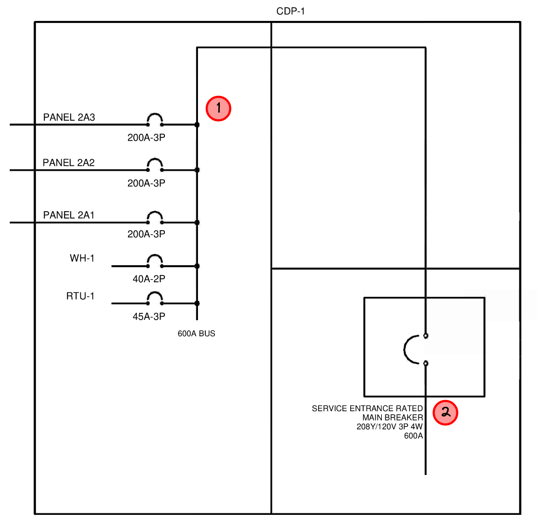
In the example above, the configuration shows multiple loads connected to a 600A bus. The main bus goes through a transition compartment into a main breaker compartment. Point "1" shows where a fault could occur on the main bus. Here the fault is downstream of the main breaker. The main breaker is adequately isolated from the fault location as it is in a separate metal compartment. This isolation ensures that the main breaker can reliably clear the fault, protecting the rest of the system. Since the device is isolated, it remains unaffected by the fault and can de-energize the circuit effectively.
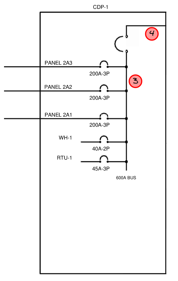
In the example above, the configuration shows multiple loads connected to a 600A bus. Point "3" is the main bus and it indicates where a fault could occur. The main breaker is in the same compartment as the main bus. They are not separated by any physical barriers. Because the protective device is not adequately isolated from the fault location, a main bus fault can potentially compromise the ability of the main breaker to operate OR the fault could propagate to the line side of this main breaker. The lack of isolation means one cannot rely on the main breaker to clear the fault. The upstream protective device (not in picture) must now be considered for clearing the fault.
The main difference between the two examples is the presence of isolation. In the second example, the lack of isolation from the fault (point 3) means the main breaker can be compromised by the fault, rendering it ineffective. In the first example, the isolation from the fault (point 1) to the device required to clear the fault (point 2) allows the fault to be cleared, ensuring reliable protection for the system.
Protective device isolation is the practice of physically separating the protective device from a potential electrical fault location to ensure the device can reliably clear the fault without being compromised.
Effects of Main Protective Device Isolation on Arc Flash
Now that we understand if a protective device is physically isolated from the fault location, let's review what effects this can have on arc flash incident energy.
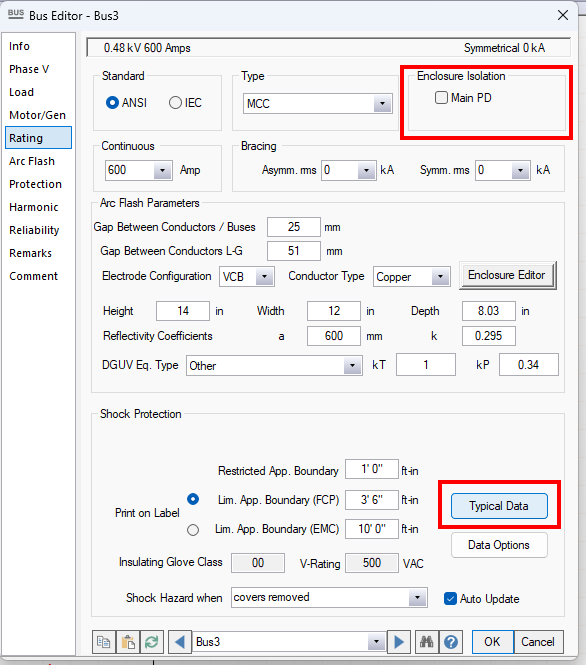
Below is an example of two simple systems, modelled in ETAP. The two radial systems are identical with exception of one thing — BusWithPDIsolation has the checkbox Enclosure Isolation: Main PD toggled ON, while BusWithoutPDIsolation has the checkbox Enclosure Isolation: Main PD toggled OFF.
.jpg)
The system on the left has drastically different arc flash values between the line side of the main breaker and the main bus. This system, with Enclosure Isolation: Main PD toggled ON, can rely on the main breaker CB1 to clear the fault. As the main breaker typically has more aggressive protection set points compared to the upstream transformer's primary fuse trip curve, the arc flash on the main bus is much lower than the line side of the CB1.
Conversely, the system on the right has the same (high) arc flash values on the line side of the main breaker and the main bus. With Enclosure Isolation: Main PD toggled OFF, we are telling ETAP that this main breaker CB1 is not isolated from a fault on the bus and therefore we cannot rely on it to clear the fault. As a result, a fault on either bus must be cleared by the transformer's primary fuse resulting in the same high arc flash value.
This example demonstrates that physically isolating a protection device from the downstream bus can significantly reduce arc flash energy on the bus.
How to use protective device isolation in ETAP
We set up enclosure isolation from the main protective device in the bus editor, not the protective device editor.
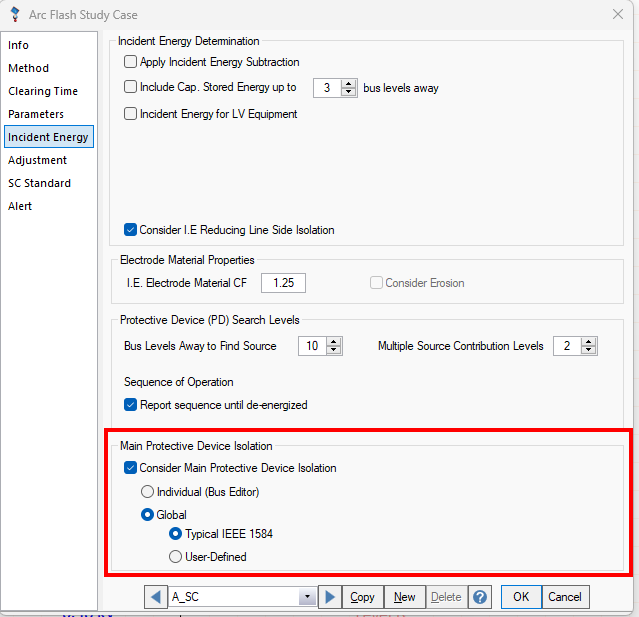
Arc Flash Study Case has settings to enable ETAP defaults for "Main Protective Device Isolation", or look at each bus individually.
Different types of equipment have different levels of isolation varies across different types of equipment. Here's an insight into typical defaults:
- Switchgear: The main protective device is typically physically isolated due to switchgear construction that includes breaker cubicles. The cubicle provides isolation between a downstream bus fault and the device that is intended to clear this fault.
- Switchboards and Panelboards: The main protective device is typically not isolated, as these designs can lack sufficient physical barriers. The main is in the same compartment as the bus — a fault on the bus means the main could be compromised or the fault can extend to the line-side of the main.
- Motor Control Centers (MCCs): Typically not considered isolated.
- Open Air and Cable Bus: Generally regarded as isolated owing to their operational environment.
Default settings in ETAP prioritize safety by assuming no adequate isolation unless proven otherwise. This conservative approach is balanced by encouraging thorough inspection and evaluation for each specific situation. This ensures that arc flash studies account for higher risk, providing more conservative and safer results. Click "Typical Data" in the bus editor to reset the protective device isolation settings to the default values.
Consider the implications for switchgear construction, where breakers are enclosed in cubicles. Arc flashes on the load side of the main breaker or bus are typically protected by the main breaker. The energy level on the main bus is usually lower because the main breaker trips before an upstream device. In this setup, protective device isolation significantly influences arc fault energy calculations.
Conclusion
When working with protective device isolation, several operational elements come into play. For instance, in ETAP's calculation methodology, the option for main PD isolation allows for more conservative results by assuming various isolation states. Checking this option assumes adequate isolation, enabling the main PD to de-energize a bus arc fault before escalation. If unchecked, it assumes insufficient isolation, treating directly connected source PDs as ineffective, thus leveraging upstream devices.
Protective device isolation is vital for electrical system safety, as improper isolation can render the device ineffective during faults, necessitating reliance on upstream devices. And improper modelling of protective device isolation can result in higher arc flash values than the arc flash label indicates.